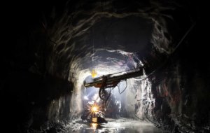
Microtunnelling: definition and possible applications
Microtunnelling is an underground tunnelling technique used for the construction of utility tunnels with a diameter of approximately 500 mm to 4,000 mm. Since these tunnels have a comparatively small diameter, it is not possible for an operator to directly control the tunnel boring machine. Therefore, the machines have to be controlled remotely from a control panel in a specially equipped control room at ground level.
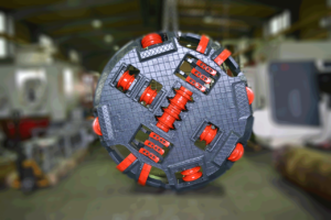
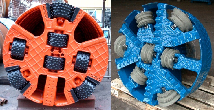
Microtunnelling machines
Micro tunnel boring machines are very similar to normal tunnel boring machines, but are smaller in size. These machines usually vary between 0.65 and 4.0 metres in diameter at the cutting head, but there are also smaller and larger machines.
The machines are usually controlled remotely from a control room on the surface. The microtunnelling machine and the jacking frame are set up in a shaft at the desired depth. The operator receives constant information about the machine’s location, alignment and hydraulic equipment via a computer console, CCTV camera or gyro unit. Some systems are equipped with video cameras that allow the operator to monitor the activities in the drivage shaft and at the separation plant. The operator controls the MTBM and the jacking frame from the control room, which is usually located at the surface, next to the jacking shaft. Newer generation machines use a Gyro Control location and send digital feedback to the control panel.
In most microtunnelling projects, the machine is started by a drive-in eye, the pipes are then guided behind the machine and laid. This process is often called pipe jacking and is repeated until the machine reaches the receiving shaft. As the machine moves forward, more tunnel liner or pipe is pushed from the launch shaft through the entry eye. The speed of the advancing machine is therefore controlled by the speed at which the pipe is inserted into the entry eye via the extension of the hydraulic cylinders in the advance frame.
The problem of ground friction
As the length of the tunnel increases, the friction of the soil around the pipe increases proportionally. Two methods are usually used to minimise this friction. Firstly, an overcut is used to create a slight gap between the inner edge of the tunnel and the outer edge of the liner. Normally this is achieved by using a cutting wheel with a diameter 12 – 35 mm larger than the outer diameter of the liner. Secondly, a lubricant, often bentonite slurry, is injected into this gap. In addition to lubrication, the pressure of the lubricant prevents the gap from collapsing. Overcutting of more than 35 mm has been shown to cause ground subsidence, depending on the geology. For road and rail crossings, this 35 mm is reduced so that no more than 10 mm lowering is possible.
Although friction can be reduced, it can never be completely eliminated. Therefore, hundreds of tonnes of force are sometimes required to drive the machine and the liner in the ground. To generate these forces, a large “jacking frame” with hydraulic cylinders is needed. In most cases, the entrance shaft must be strong enough to support the forces generated.
In addition to the jacking frame, smaller jacking cylinders – so-called “interjacks” – can be used between the sections of the tunnel lining. These push the two sections of the lining apart. The friction on the liner sections between the intermediate trestle and the tunnel entrance prevents the liner from slipping out backwards. So while the liner behind the spacer does not move, the sections in front of the spacer receive additional thrust.